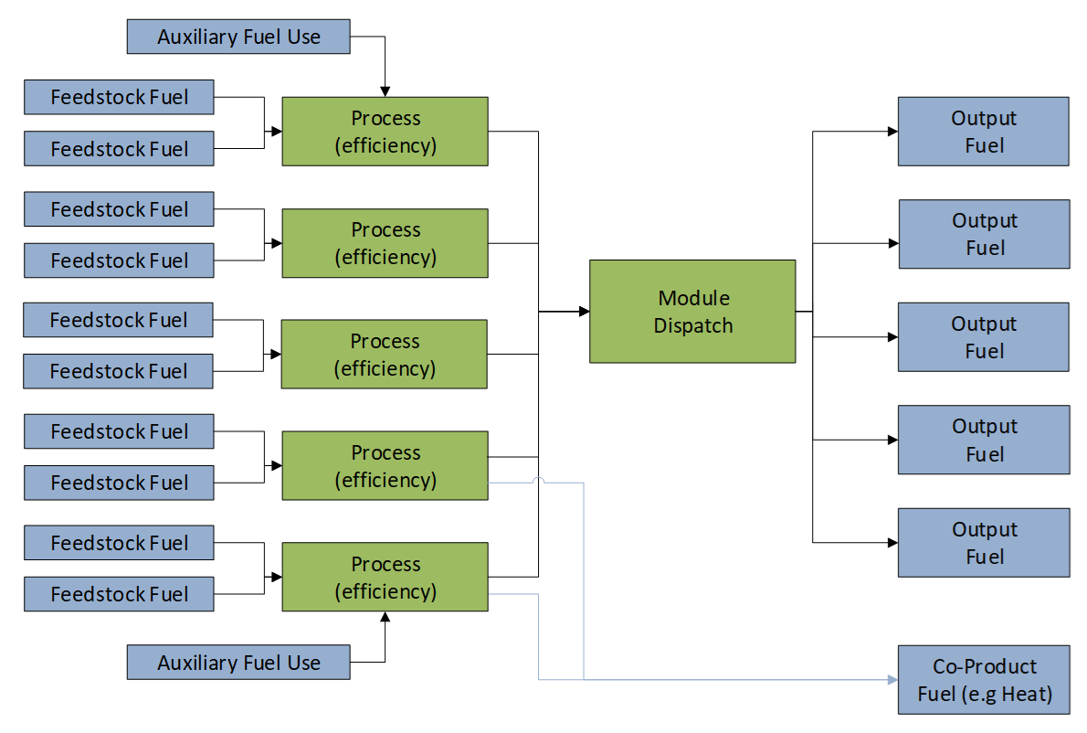
Schematic of a Transformation Module
See also: Analysis View, Transformation Analysis, Module Properties
Below is a general schematic for a typical detailed Transformation module. Notice that each module can have multiple processes, which are dispatched together to try and meet their requirements for the module's one or more output fuels. Each process can have multiple feedstock fuels and multiple auxiliary fuels. Feedstock fuels are converted into output fuels at the rated thermal efficiency of each process. Energy consumed in auxiliary fuel use is NOT included in efficiency of a process. Each process may also produce a co-product (e.g. heat). Only one co-product can be specified for each module. However, the co-product can be produced at different rates (or not at all) by different processes as specified in the process co-product efficiency variable. For each process, efficiency + co-product efficiency must be less than or equal to 100%.
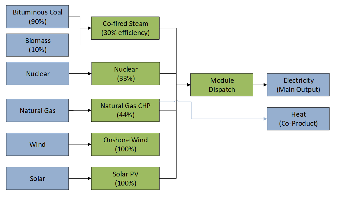
This general schematic can look very different in practice when applied to different Transformation sectors. Below we show two examples for electricity generation and oil refining.
Electricity Generation Schematic
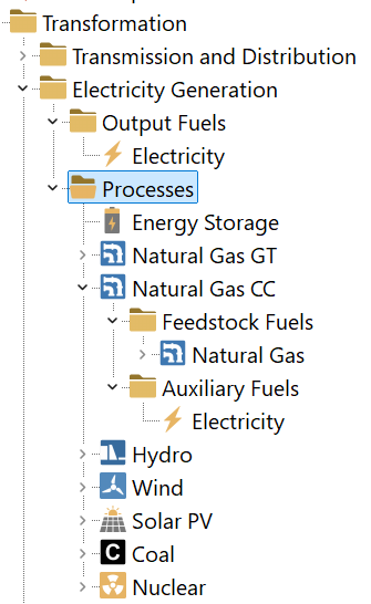
Compare the above graphic to the screenshot below which shows the same basic information as it appears within LEAP's tree structure:
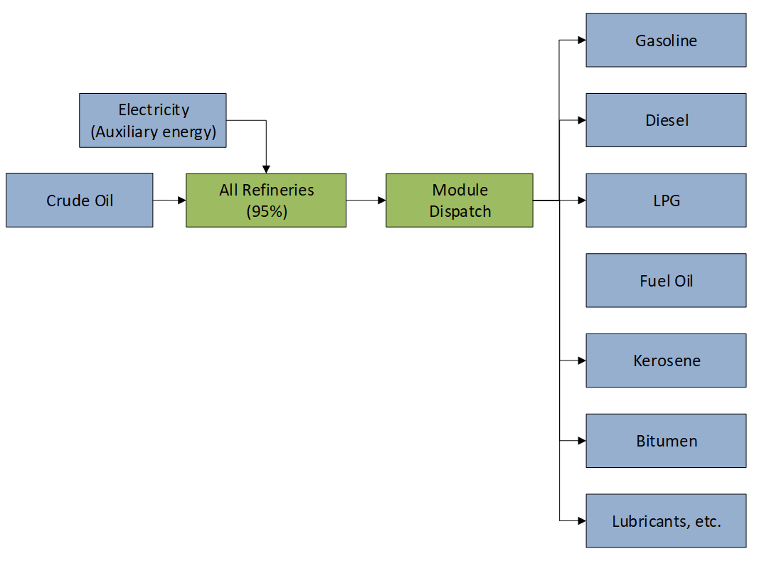
Oil Refining Schematic
Simple Modules
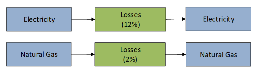
Finally, it is worth noting that you can also create "simple" modules. These modules simply contain a list of processes that are dispatched independently of one another as shown in the schematic below.