Setting Up Transmission Modeling
See also: Transmission Nodes, Transmission Lines, Optimization Modeling
In multi-regional models, LEAP supports least-cost optimization of pipelines and transmission networks. With this facility, you can set up candidate transmission lines that run between nodes located in the different regions of your model and, during its least-cost optimization calculations, LEAP and NEMO's will choose how much of the networks to build and how much energy will flow through the network lines in each time slice of every year (and in what direction).
There are number of steps you most follow to enable transmission modeling. These are described below.
Install NEMO
First make sure you have installed NEMO. NEMO is the optimization framework used by LEAP and any optimization calculations require the presence of NEMO. NEMO is available from the same download page as LEAP. Once NEMO is installed, it will automatically integrate with LEAP without further intervention. You can check that LEAP recognizes the presence of NEMO by going to LEAP's Help: About screen and looking for an entry for NEMO followed by its version number (e.g. "NEMO: 2.00"). Full energy system optimization and transmission modeling require the presence of NEMO v2.00 or later. If you plan on using a commercial solver with NEMO (such as CPLEX, GUROBI or XPress), make sure they are installed first before you install NEMO. NEMO compiles itself upon installation including the components used to connect to these commercial solvers, so there presence is required during NEMO's installation. Should you accidentally install NEMO first, simply uninstall it, install the required solver and then reinstall NEMO. Note that the free open-source solvers Cbc, HIGHS, and GLPK are built-in to NEMO. No additional installation is required if you want to use them.
Enable Transmission Networks
Once NEMO is properly installed, go to the Optimization tab of the General Settings screen and choose a setting for the Transmission Networks option as shown below. You can switch off transmission modeling entirely by selecting No or you can choose between Continuous Build and Discrete Build modeling of transmission networks. This setting determines whether NEMO's optimization calculations use binary or continuous variables to represent the construction of candidate transmission lines. When set to Discrete Build, candidate lines may only be built in their entirety (their size defined by the Transmission Capacity variable). When set to Continuous Build, partial line construction is allowed. Continuous build simulations are generally faster but may not be as realistic. If the Transmission Networks setting is set to No, then all data related to transmission modeling will be hidden and transmission networks will not be modeled. Any related data is not deleted however: it will reappear if you later switch the setting back on.

Enable Full Energy System Optimization
Next, ensure you are working in a scenario that uses full energy system optimization (ESO) calculations. Transmission network calculations are not supported when Transformation is modeled using LEAP's simulation or partial optimization calculations. To enable ESO, enter the value Yes in the Energy System Optimization variable located at the top level (Area) branch for relevant scenarios.
Check for Multi-Region Modeling
Transmission modeling is currently only available for multi-region models, since it is deigned to model the possible transmission networks connecting those regions, so be sure to check that your model contains multiple regions.
Create Transmission Nodes and Transmission Lines
Once you have completed the above steps, you are ready to create the list of transmission nodes and the candidate lines connecting those nodes. In Analysis View, use the General: Transmission Nodes screen to create nodes in each region. Then use the General:Transmission Lines screen to create candidate lines connecting those nodes. For each line you will select a From and a To node. Note that energy can flow in either direction in any given time slice depending on the cost and availability of energy supplies in each region (and the amount of energy storage in each region). The From and To designations are merely designed to allow LEAP to display results in a way that is consistent and easy to interpret. By convention, energy flows are displayed as positive values when they flow from the From node to the To node. Energy flows are shown as negative values when they flow in the reverse direction. To avoid confusion, LEAP requires that the from/to node ordering must be the same for all lines connecting the same regions. For example, you cannot have one line from England to France and another from France to England.
Tip: you can specify if a line is enabled using the check box on the far right of the table in The Transmission Lines screen. Any lines that are not enabled will not appear in the LEAP tree and will not be included in LEAP's transmission network modeling. Use the enabled property if you want to temporarily exclude certain lines from your analysis.
Connect Nodes to Your Transmission Modules
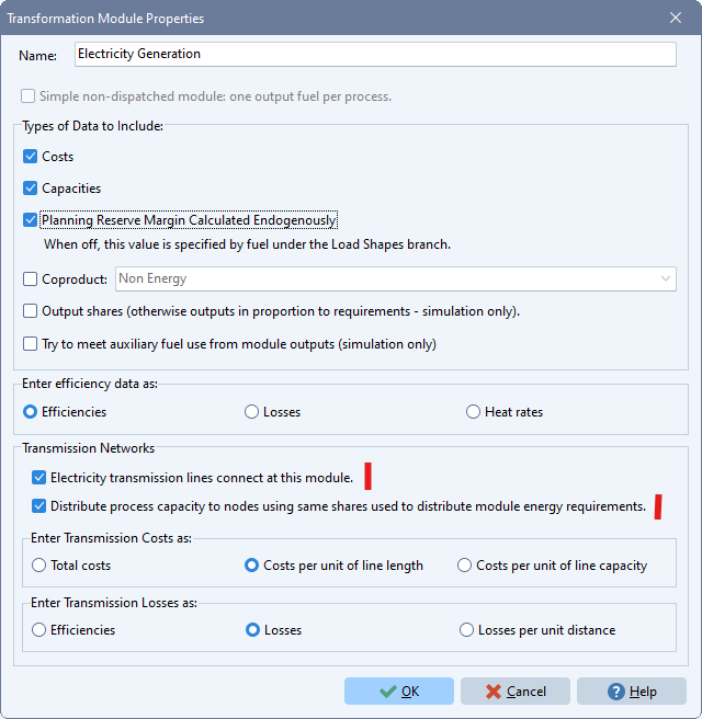
Next, you will connect these nodes and lines to relevant Transformation modules For example, if you are modeling an electricity transmission network, you will connect that network to a Transformation module that produces electricity (e.g. an electricity generation module). To do this, in the Analysis View right-click on a Transformation module in the Tree and select its Properties screen as shown below.

Use the first checkbox marked above to select that a fuel's "transmission lines connect at this module". You can also optionally specify how you want to enter data describing transmission costs and losses, and how you want to distribute the module's capacity among transmission nodes (required for cases where there is more than one node per region). By default, and to keep data entry to a minimum, you can select that capacity is distributed in the same way as the overall energy requirements on the module as a whole. If you uncheck this box, you can distribute capacity to nodes separately for each process in the module.
Enter Data Describing Your Transmission Lines
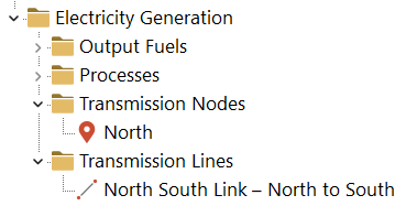
Once you have connected a Transformation module to a transmission network, additional branches and variables will appear in the tree under the relevant Transformation module in Analysis View. Transmission variables are only visible when editing a scenario in which transmission modeling is enabled. As shown below, you will see two category branches listing the Transmission Nodes and Transmission Lines. Under these categories you will see branches listing particular nodes and lines. The list of nodes and lines will depend on what region your are working on (as selected via the Region selection box at the top of the screen).

For the transmission nodes, enter Nodal Distribution Shares, allocating the module's energy requirement to each node. These shares must sum to 100% across all nodes in each region. If there is just one node, simply enter 100% (or use the expression "Remainder(100)".
For the transmission lines enter data describing each candidate line including the maximum capacity, capital and O&M costs and related data such as line losses, maximum availability, lifetimes and interest rates.
Note also that you will need to specify the type of simulation used to model each transmission line using the simulation type variable and the associated NetworkSimulation function. This variable is specified at the Tranbsmonce for each set of lines
Viewing Results
Once you have completed entering data for your transmission networks LEAP and NEMO will include consideration of those networks in the overall scenario calculations, deciding how much of each line to build and what are the optimum energy flows through each line in each time slice of every year.
The results of those calculations are available in the Results View under the Transmission category. Three types of results can be viewed: Transmission Capacity, Transmission Power Flows and Transmission Energy Flows.
For additional information, please consult the NEMO Documentation.